
Garegin Tadevosyan
Verified Expert in Engineering
Garegin是一名精通Unity和c#的游戏开发者. 他为游戏化的操场设备创建了一个网络协议, 曾担任一家教育游戏初创公司的首席技术官, 他是一家跨国社交赌场团队的游戏开发者.
Previously At

Garegin是一名精通Unity和c#的游戏开发者. 他为游戏化的操场设备创建了一个网络协议, 曾担任一家教育游戏初创公司的首席技术官, 他是一家跨国社交赌场团队的游戏开发者.
In “Unity AI开发:有限状态机教程,“我们创造了一款简单的潜行游戏——基于fsm的模块化AI. 在游戏中,一名敌方特工在游戏空间巡逻. 当敌人发现玩家时,它会改变自己的状态并跟随玩家而不是巡逻.
In this second leg of our Unity journey, 我们将构建一个图形用户界面(GUI),以便更快地创建有限状态机(FSM)的核心组件, 并且具有改进的开发人员体验.
上一篇教程中详细介绍的FSM是由架构块构建而成的 C# scripts. We added custom ScriptableObject actions and decisions as classes. Our ScriptableObject 方法允许我们拥有一个易于维护和定制的FSM. 在本教程中,我们将替换FSM的拖放操作 ScriptableObjects with a graphical option.
In your game, 如果你想让玩家更容易获胜, 用这个替换玩家检测脚本 updated script 这会缩小敌人的视野.
我们将使用以下命令构建图形化编辑器 xNode一个基于节点的行为树框架,可以可视化地显示FSM的流程. Although Unity’s GraphView 能完成这项工作,它的API是实验性的和贫乏的文档. xNode的用户界面提供了卓越的开发人员体验, 促进我们的FSM原型和快速扩展.
Let’s add xNode to our project 作为Git依赖使用Unity包管理器:
http://github.com/siccity/xNode.git 在未标记的文本框中,单击 Add button.现在我们准备深入了解xNode的关键组件:
Node class | 表示节点,即图中最基本的单位. 在本xNode教程中,我们从 Node 类的新类声明配备自定义功能和角色的节点. |
NodeGraph class | 表示节点的集合(Node 类实例)和连接它们的边. 在本xNode教程中,我们从 NodeGraph 操作和计算节点的新类. |
NodePort class | 表示通信门,即类型输入或类型输出的端口,位于 Node instances in a NodeGraph. The NodePort class is unique to xNode. |
[Input] attribute | The addition of the [Input] 属性将端口指定为输入, 使端口能够将值传递给它所属的节点. Think of the [Input] attribute as a function parameter. |
[Output] attribute | The addition of the [Output] 属性将端口指定为输出, 允许端口从它所属的节点传递值. Think of the [Output] 属性作为函数的返回值. |
在xNode中,我们使用每个 State and Transition takes the form of a node. 输入和/或输出连接使节点能够与图中的任何或所有其他节点相关联.
让我们想象一个有三个输入值的节点:两个任意值,一个布尔值. 节点将输出两个任意类型输入值中的一个, 取决于布尔输入是真还是假.

Branch Node要将现有的FSM转换为图,我们修改 State and Transition classes to inherit the Node class instead of the ScriptableObject class. We create a graph object of type NodeGraph to contain all of our State and Transition objects.
BaseStateMachine to Use As a Base Type我们将通过向现有的虚拟方法中添加两个新的虚拟方法来开始构建图形界面 BaseStateMachine class:
Init | Assigns the initial state to the CurrentState property |
Execute | Executes the current state |
将这些方法声明为虚方法允许我们重写它们, 类的自定义行为 BaseStateMachine 类初始化和执行:
using System;
using System.Collections.Generic;
using UnityEngine;

namespace Demo.FSM
{
    公共类basestatemmachine: MonoBehaviour
    {
        [SerializeField] private BaseState _initialState;
        private Dictionary _cachedComponents;
        private void Awake()
        {
            Init();
            _cachedComponents = new Dictionary();
        }

        public BaseState CurrentState { get; set; }

        private void Update()
        {
            Execute();
        }

        public virtual void Init()
        {
            CurrentState = _initialState;
        }

        public virtual void Execute()
        {
            CurrentState.Execute(this);
        }

       //允许我们在0(1)时间内连续调用GetComponent
        public new T GetComponent() where T : Component
        {
            if(_cachedComponents.ContainsKey(typeof(T)))
                return _cachedComponents[typeof(T)] as T;

            var component = base.GetComponent();
            if(component != null)
            {
                _cachedComponents.Add(typeof(T), component);
            }
            return component;
        }

    }
}
Next, under our FSM folder, let’s create:
FSMGraph | A folder |
BaseStateMachineGraph | A C# class within FSMGraph
|
For the time being, BaseStateMachineGraph will inherit just the BaseStateMachine class:
using UnityEngine;

namespace Demo.FSM.Graph
{
    BaseStateMachineGraph: basestatemmachine
    {
    }
}
We can’t add functionality to BaseStateMachineGraph until we create our base node type; let’s do that next.
NodeGraph and Creating a Base Node TypeUnder our newly created FSMGraph folder, we’ll create:
FSMGraph | A class |
For now, FSMGraph will inherit just the NodeGraph 类(没有添加功能):
using UnityEngine;
using XNode;

namespace Demo.FSM.Graph
{
    [CreateAssetMenu(menuName = "FSM/FSM Graph")]
    public class FSMGraph : NodeGraph
    {
    }
}
在为节点创建类之前,让我们添加:
FSMNodeBase | 一个被所有节点用作基类的类 |
The FSMNodeBase class will contain an input named Entry of type FSMNodeBase 使我们能够将节点彼此连接起来.
我们还将添加两个辅助函数:
GetFirst | 检索连接到请求输出的第一个节点 |
GetAllOnPort | 检索连接到请求输出的所有剩余节点 |
using System.Collections.Generic;
using XNode;

namespace Demo.FSM.Graph
{
    公共抽象类FSMNodeBase: Node
    {
        [输入(backingValue = ShowBackingValue ..Never)] public FSMNodeBase Entry;

        protected IEnumerable GetAllOnPort(string fieldName) where T : FSMNodeBase
        {
            NodePort port = GetOutputPort(fieldName);
            for (var portIndex = 0; portIndex < port.ConnectionCount; portIndex++)
            {
                yield return port.GetConnection(portIndex).node as T;
            }
        }

        protected T GetFirst(string fieldName) where T : FSMNodeBase
        {
            NodePort port = GetOutputPort(fieldName);
            if (port.ConnectionCount > 0)
                return port.GetConnection(0).node as T;
            return null;
        }
    }
}
Ultimately, we’ll have two types of state nodes; let’s add a class to support these:
BaseStateNode | A base class to support both StateNode and RemainInStateNode
|
namespace Demo.FSM.Graph
{
    公共抽象类BaseStateNode: FSMNodeBase
    {
    }
}
Next, modify the BaseStateMachineGraph class:
using UnityEngine;
namespace Demo.FSM.Graph
{
    BaseStateMachineGraph: basestatemmachine
    {
        public new BaseStateNode CurrentState { get; set; }
    }
}
Here, we’ve hidden the CurrentState 属性继承自基类,并将其类型更改为 BaseState to BaseStateNode.
现在,为了形成FSM的主要构建块,让我们向我们的 FSMGraph folder:
StateNode | Represents the state of an agent. On execute, StateNode iterates over the TransitionNodeS连接到输出端口 StateNode (retrieved by a helper method). StateNode 查询每个节点是否将节点转换为不同的状态,还是保持节点的状态不变. |
RemainInStateNode | 指示节点应保持当前状态. |
TransitionNode | 做出转换到不同状态或保持相同状态的决定. |
在之前的Unity FSM教程中, State 类在转换列表上迭代. Here in xNode, StateNode serves as State的方法等价于迭代通过 GetAllOnPort helper method.
Now add an [Output] 属性设置为传出连接(转换节点),以表明它们应该是GUI的一部分. By xNode’s design, 属性的值起源于源节点:该节点包含标记为 [Output] attribute. As we are using [Output] and [Input] 属性来描述将由xNode GUI设置的关系和连接, 我们不能像平常那样对待这些值. Consider how we iterate through Actions versus Transitions:
using System.Collections.Generic;
namespace Demo.FSM.Graph
{
    [CreateNodeMenu("State")]
    公共密封类StateNode: BaseStateNode
    {
        public List Actions;
        [Output] public List Transitions;
        执行BaseStateMachineGraph (BaseStateMachineGraph)
        {
            foreach (var action in Actions)
                action.Execute(baseStateMachine);
            foreach (var transition in GetAllOnPort(nameof(Transitions)))
                transition.Execute(baseStateMachine);
        }
    }
}
In this case, the Transitions output can have multiple nodes attached to it; we have to call the GetAllOnPort 控件的列表 [Output] connections.
RemainInStateNode is, by far, our simplest class. Executing no logic, RemainInStateNode 只是指示我们的代理(游戏邦注:在游戏中是敌人)保持当前状态:
namespace Demo.FSM.Graph
{
    [CreateNodeMenu("保持状态")]
    公共密封类RemainInStateNode: BaseStateNode
    {
    }
}
At this point, the TransitionNode 类仍然不完整,无法编译. 一旦我们更新了类,相关的错误将被清除.
To build TransitionNode, 我们需要绕过xNode的要求,即输出的值起源于源节点—正如我们在构建时所做的那样 StateNode. A major difference between StateNode and TransitionNode is that TransitionsNode的输出只能附加到一个节点. In our case, GetFirst 将获取连接到每个端口的一个节点(一个状态节点在true情况下转换到另一个状态节点在false情况下转换到另一个状态节点):
namespace Demo.FSM.Graph
{
    [CreateNodeMenu("Transition")]
    公共密封类TransitionNode: FSMNodeBase
    {
        public Decision Decision;
        [输出]public BaseStateNode;
        [输出]public BaseStateNode false;
        执行BaseStateMachineGraph中的stateMachine
        {
            var trueState = GetFirst(nameof(TrueState));
            var falseState = GetFirst(nameof(FalseState));
            var decision = Decision.Decide(stateMachine);
            if (decision && !(trueState is RemainInStateNode))
            {
                stateMachine.CurrentState = trueState;
            }
            else if(!decision && !(falseState is RemainInStateNode))
                stateMachine.CurrentState = falseState;
        }
    }
}
让我们看一下代码的图形化结果.
Now, 所有FSM类都被整理好了, 我们可以继续为游戏中的敌人创建FSM图. 在Unity项目窗口中,右键单击 EnemyAI folder and choose: Create > FSM > FSM Graph. 为了使我们的图更容易识别,让我们重命名它 EnemyGraph.
在xNode Graph编辑器窗口中,右键单击显示一个下拉菜单列表 State, Transition, and RemainInState. 如果窗口不可见,双击 EnemyGraph 文件启动xNode图形编辑器窗口.
To create the Chase and Patrol states:
Right-click and choose State to create a new node.
Name the node Chase.
返回到下拉菜单,选择 State again to create a second node.
Name the node Patrol.
Drag and drop the existing Chase and Patrol 动作到它们新创建的相应状态.
To create the transition:
Right-click and choose Transition to create a new node.
Assign the LineOfSightDecision object to the transition’s Decision field.
To create the RemainInState node:
To connect the graph:
Connect the Patrol node’s Transitions output to the Transition node’s Entry input.
Connect the Transition node’s True State output to the Chase node’s Entry input.
Connect the Transition node’s False State output to the Remain In State node’s Entry input.
The graph should look like this:

图中没有显示是哪个节点 Patrol or Chase state—is our initial node. The BaseStateMachineGraph 类检测四个节点,但由于没有指示器,因此无法选择初始状态.
为了解决这个问题,让我们创建:
FSMInitialNode | 类的唯一输出类型为 StateNode is named InitialNode
|
Our output InitialNode denotes the initial state. Next, in FSMInitialNode, create:
NextNode | 属性,使我们能够获取连接到的节点 InitialNode output |
using XNode;
namespace Demo.FSM.Graph
{
    [CreateNodeMenu("Initial Node"), NodeTint("#00ff52")]
    公共类fsminialnode:节点
    {
        [输出]public StateNode InitialNode;
        public StateNode NextNode
        {
            get
            {
                var port = GetOutputPort(“InitialNode”);
                if (port == null || port.ConnectionCount == 0)
                    return null;
                return port.GetConnection(0).node as StateNode;
            }
        }
    }
}
Now that we created theFSMInitialNode class, we can connect it to the Entry 方法输入初始状态,并返回初始状态 NextNode property.
让我们回到图中,添加初始节点. In the xNode editor window:
Patrol node’s Entry input.图形现在看起来应该是这样的:

为了让我们的生活更轻松,我们将添加到 FSMGraph:
InitialState | A property |
我们第一次尝试找回 InitialState property’s value, 属性的getter将遍历图中的所有节点 FSMInitialNode. Once FSMInitialNode is located, we use the NextNode 属性查找初始状态节点:
using System.Linq;
using UnityEngine;
using XNode;
namespace Demo.FSM.Graph
{
    [CreateAssetMenu(menuName = "FSM/FSM Graph")]
    公共密封类FSMGraph: NodeGraph
    {
        private StateNode _initialState;
        public StateNode InitialState
        {
            get
            {
                if (_initialState == null)
                    _initialState = FindInitialStateNode();
                return _initialState;
            }
        }
        private StateNode findininitialstatenode
        {
            var initialNode = nodes.FirstOrDefault(x => x is FSMInitialNode);
            if (initialNode != null)
            {
                返回(initialNode作为fsminialnode).NextNode;
            }
            return null;
        }
    }
}
Now, in our BaseStateMachineGraph, let’s reference FSMGraph and override our BaseStateMachine’s Init and Execute methods. Overriding Init sets CurrentState 作为图形的初始状态,并重写 Execute calls Execute on CurrentState:
using UnityEngine;
namespace Demo.FSM.Graph
{
    BaseStateMachineGraph: basestatemmachine
    {
        [SerializeField] private FSMGraph _graph;
        public new BaseStateNode CurrentState { get; set; }
        public override void Init()
        {
            CurrentState = _graph.InitialState;
        }
        public override void Execute()
        {
            ((StateNode)CurrentState).Execute(this);
        }
    }
}
现在,让我们将我们的图形应用到敌人对象上,看看它的实际情况.
在准备测试时,在Unity编辑器的项目窗口中,我们需要:
Open the SampleScene asset.
Locate our Enemy 在Unity层次窗口中的游戏对象.
Replace the BaseStateMachine component with the BaseStateMachineGraph component:
Click Add Component and select the correct BaseStateMachineGraph script.
Assign our FSM graph, EnemyGraph, to the Graph field of the BaseStateMachineGraph component.
Delete the BaseStateMachine 组件(因为不再需要它),通过右键单击并选择 Remove Component.
Now the Enemy game object should look like this:
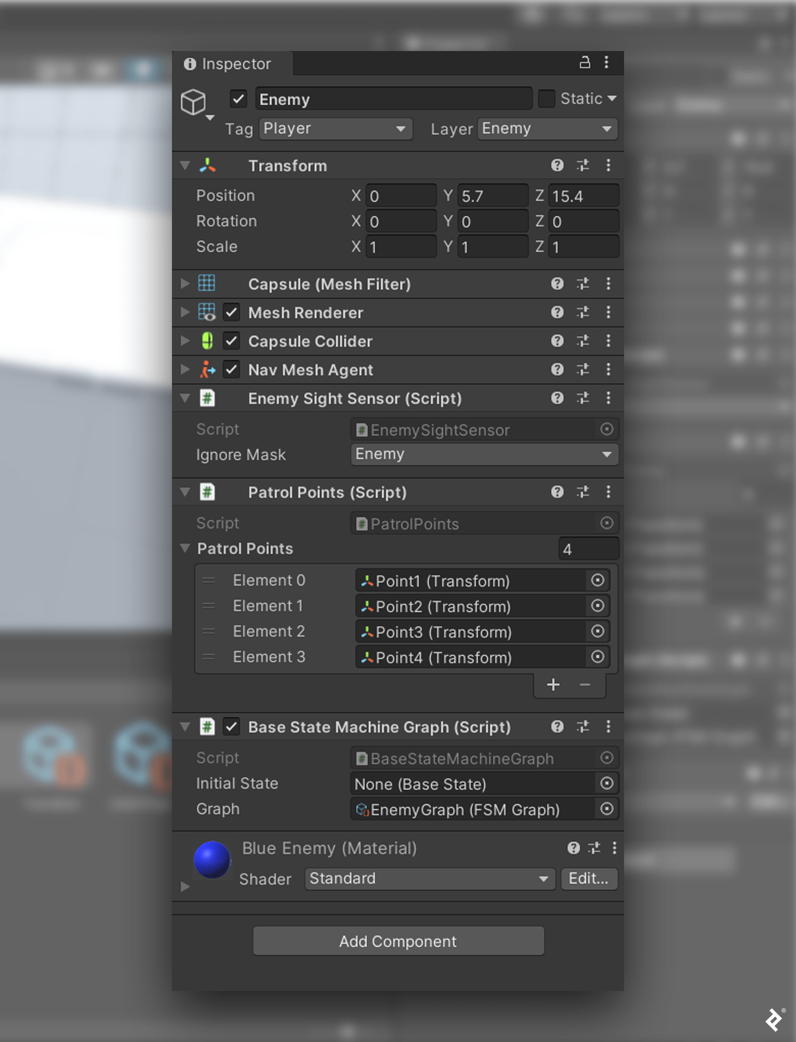
Enemy Game ObjectThat’s it! Now we have a modular FSM with a graphic editor. When we click the Play 按钮时,我们看到图像上的敌人AI和之前的完全一样 ScriptableObject enemy.
使用图形化编辑器的优点是不言而喻的, 但我要提醒你一句:当你为游戏开发更复杂的AI时, 状态和转换的数量会增加, FSM变得令人困惑,难以阅读. 图形化编辑器逐渐变得类似于一个由行组成的网络,这些行起源于多个状态,终止于多个转换,反之亦然, making our FSM difficult to debug.
As we did in the previous tutorial, 我们邀请您自己编写代码, 为你优化潜行游戏并解决这些问题留有余地. 想象一下,用颜色标记状态节点来指示节点是活动的还是不活动的,这将是多么有用, or resize the RemainInState and Initial 节点来限制它们的屏幕空间.
这种增强不仅仅是表面上的. 颜色和大小参考将帮助我们确定调试的位置和时间. 一个直观的图表也更容易评估、分析和理解. 接下来的任何步骤都取决于您,在我们的图形编辑器的基础上, 开发者体验的改进是没有限制的.
Toptal工程博客的编辑团队向 Goran Lalić 感谢Maddie Douglas审阅了本文中的代码示例和其他技术内容.
有限状态机(FSM)是一种计算模型,在给定时间只能处于一种状态. 因此,我们可以表示任何需要这种功能的系统(例如.g.(如管理交通灯或电梯)作为FSM. 我们也可以使用FSM来开发游戏AI和游戏管理系统.
添加AI是实现FSM的一种方式. In the case of an FSM, AI采用编码类和自定义动作的形式, decisions, and behaviors.
FSMs can be represented as graphs. 在理论意义上,图是顶点和边. In the case of an xNode FSM, 顶点表示状态和转换, 而边表示转换流.
FSM可以用来模拟顺序逻辑.
Located in Yerevan, Armenia
Member since July 1, 2021
Garegin是一名精通Unity和c#的游戏开发者. 他为游戏化的操场设备创建了一个网络协议, 曾担任一家教育游戏初创公司的首席技术官, 他是一家跨国社交赌场团队的游戏开发者.
 作者都是各自领域经过审查的专家,并撰写他们有经验的主题. 我们所有的内容都经过同行评审,并由同一领域的Toptal专家验证.
世界级的文章,每周发一次.
世界级的文章,每周发一次.
Join the Toptal® community.
